CS184 Project 2: Modeling Geometry
https://samkim2025.github.io/cs184/2/index.html
Overview
In this assignment, I implemented core algorithms for Bézier curve and surface evaluation, vertex normal computation, and mesh subdivision techniques, including edge flips, splits, and Loop subdivision. The Bézier curve and patch implementations use de Casteljau’s algorithm to recursively compute intermediate points, ensuring smooth interpolation. The vertex normal calculation uses area-weighted triangle normals to provide a better approximation of smooth shading. The mesh subdivision methods allow for refining geometry while maintaining consistency, leveraging edge flips and splits for uniformity. Through this work, I gained insight into the mathematical foundations of geometric modeling and the impact of different data structures on computational efficiency and accuracy.
Section 1: Bezier Curves and Surfaces
Part 1: Bezier Curves with 1D de Casteljau Subdivision
1. Briefly explain de Casteljau’s algorithm and how you implemented it in order to evaluate Bezier curves.
De Casteljau's algorithm is a recursive method to evaluate points on a Bezier curve at a given parameter value t (where t ranges from 0 to 1). The algorithm works like this:
- Start with n+1 control points that define an nth degree Bezier curve.
- For each recursive step, perform linear interpolation between adjacent points to create a new set of n points.
- Continue this process until a single point remains, which is the point on the Bezier curve at parameter t.
In my implementation, I followed this algorithm by:
- Taking the input vector of control points
- Creating a new vector to store intermediate points
- For each pair of adjacent points (p_i and p_{i+1}), computing a new point using linear interpolation:
p_i' = (1-t) * p_i + t * p_{i+1}
- Returning the new vector of intermediate points
This single step of the algorithm reduces n points to n-1 points. When called repeatedly, it eventually produces a single point lying on the Bezier curve.
2. Take a look at the provided .bzc files and create your own Bezier curve with 6 control points of your choosing. Use this Bezier curve for your screenshots below.
Bezier Curve with 6 control points
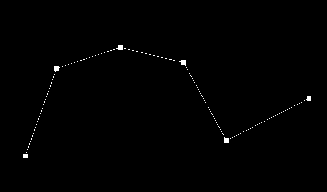
3. Show screenshots of each step / level of the evaluation from the original control points down to the final evaluated point.
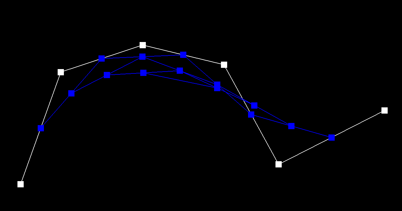
Original Bezier
The original 6 control points defining my Bezier curve.
Level 1
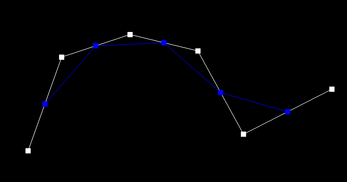
After one step of de Casteljau's algorithm, we have 5 intermediate points (blue) generated from the original control points.
Level 2
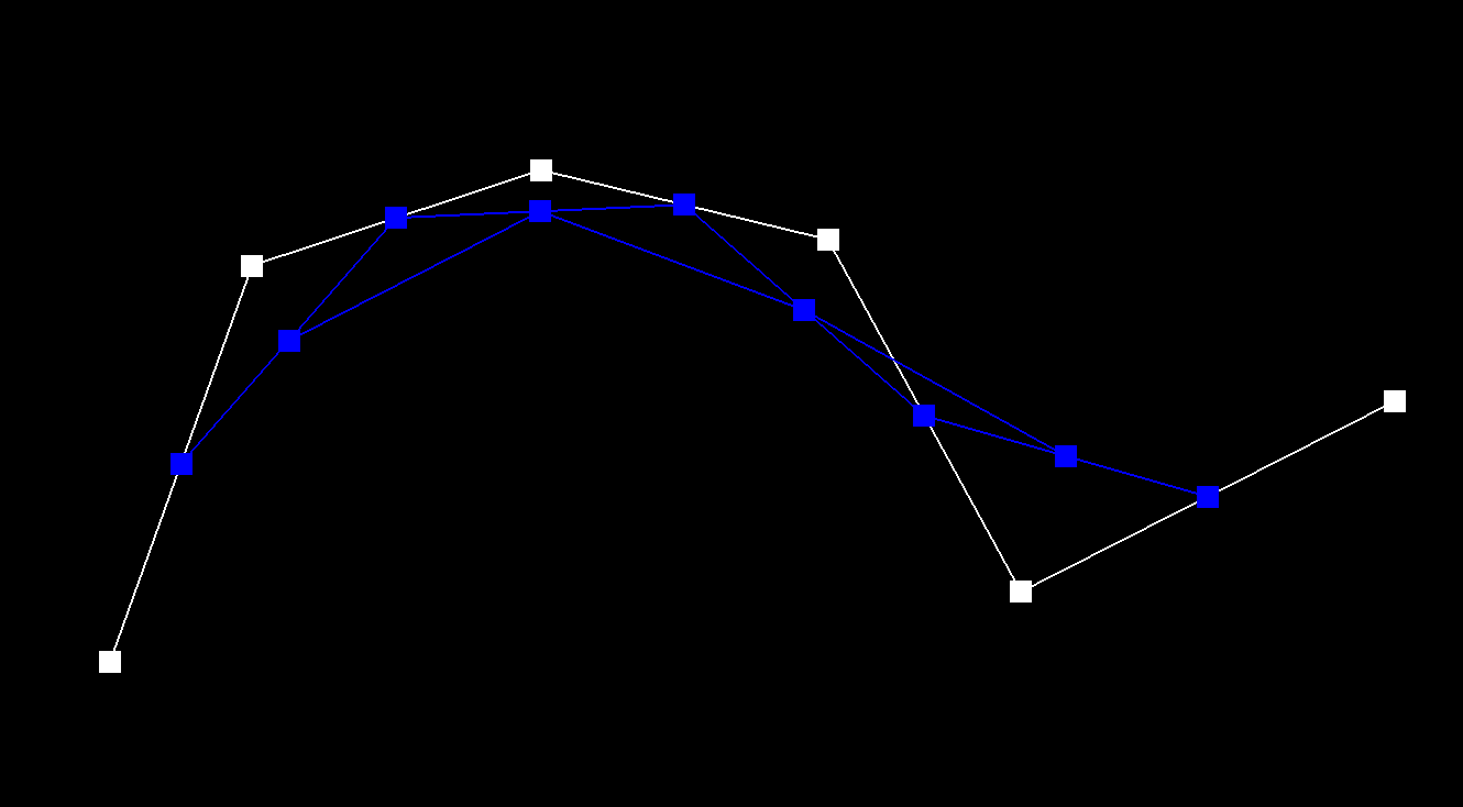
After two steps, we have 4 intermediate points (blue) generated from the previous level's points.
Level 3
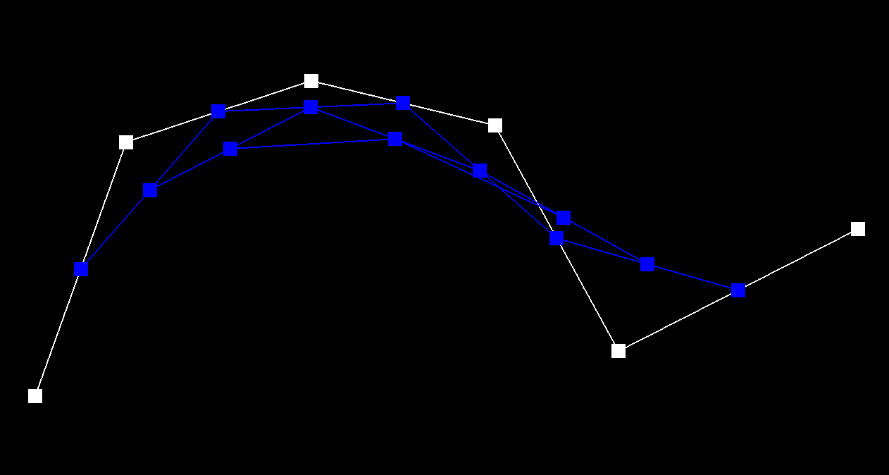
After three steps, we have 3 intermediate points (blue).
Level 4
After four steps, we have 2 intermediate points (blue).
Level 5
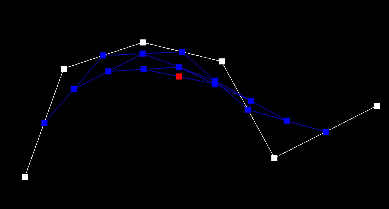
After five steps, we have the final point (red) that lies on the Bezier curve at parameter t.
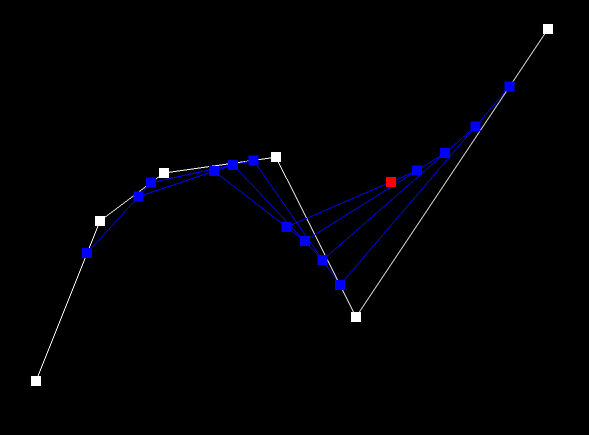
4. Show a screenshot of a slightly different Bezier curve by moving the original control points around and modifying the parameter t via mouse scrolling.
Modified Bezier Curve with t = 0.8
Part 2: Bezier Surfaces with Separable 1D de Casteljau
1. Briefly explain how de Casteljau algorithm extends to Bezier surfaces and how you implemented it in order to evaluate Bezier surfaces.
De Casteljau's algorithm extends naturally from curves to surfaces through a technique called separable 1D de Casteljau. While a Bezier curve is defined by a 1D array of control points and one parameter t, a Bezier surface is defined by a 2D grid of control points and two parameters (u,v). The algorithm works like this:
- First Parametric Direction: For each row of control points in the grid, we apply the 1D de Casteljau algorithm using parameter u. This gives us n points (where n is the number of rows).
- Second Parametric Direction: We then treat these n points as control points for another Bezier curve, and apply de Casteljau again using parameter v.
- Final Result: The result is a single point that lies on the Bezier surface at coordinates (u,v).
In my implementation:
- evaluateStep: Implements a single step of linear interpolation between adjacent 3D points, just like with curves but extended to 3D space.
- evaluate1D: Fully evaluates a Bezier curve by repeatedly applying evaluateStep until arriving at a single point.
- evaluate: Coordinates the two-direction evaluation by first applying evaluate1D to each row of control points with parameter u, then applying evaluate1D again to these intermediate results with parameter v
This approach works elegantly because it reuses the same algorithm in two directions, avoiding the need for a specialized 2D algorithm. It works because Bezier surfaces have the mathematical property of being "bi-parametric" - they can be evaluated independently in each parametric direction.
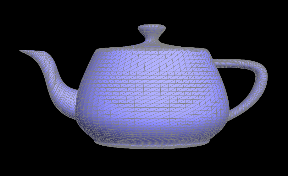
2. Show a screenshot of bez/teapot.bez (not .dae) evaluated by your implementation.
bez/teapot.bez
Section 2: Triangle Meshes and Half-Edge Data Structure
Part 3: Area-Weighted Vertex Normals
1. Briefly explain how you implemented the area-weighted vertex normals.
To implement area-weighted vertex normals, I calculated the normal at each vertex by considering all the faces (triangles) connected to it. For each face, I:
- Computed the face normal weighted by its area using the cross product of two edges of the triangle.
- Accumulated these area-weighted normals.
- Normalized the result to get a unit normal vector.
The key insight is that the cross product of two edges not only gives the direction of the normal but also has a magnitude proportional to the area of the triangle. This means that larger faces contribute more to the final normal direction, which is geometrically appropriate.
My implementation iterates around each vertex using the half-edge data structure, computing the area-weighted normal for each non-boundary face, and summing them up. This produces a normal that better represents the local geometry around the vertex, which is essential for smooth shading.
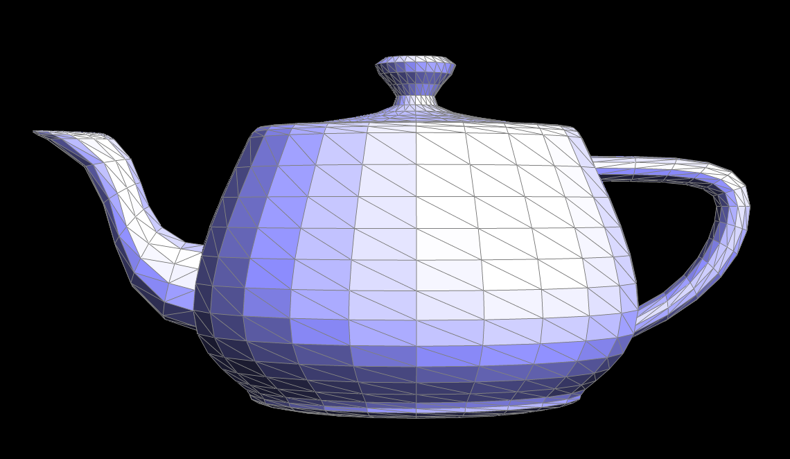
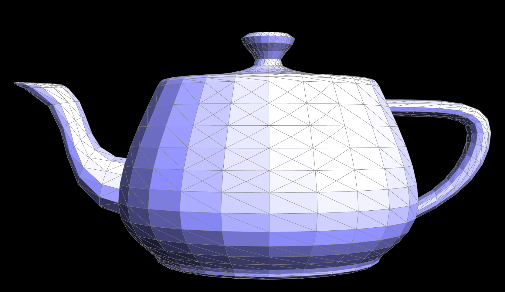
2. Show screenshots of dae/teapot.dae (not .bez) comparing teapot shading with and without vertex normals.
Default Flat Shading
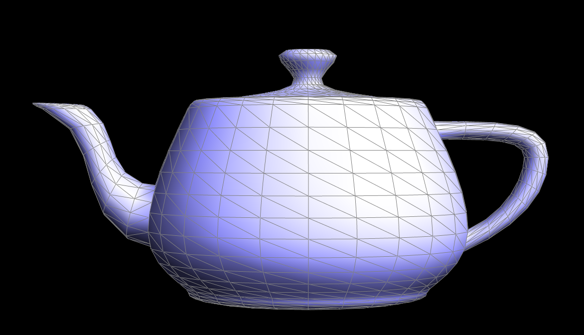
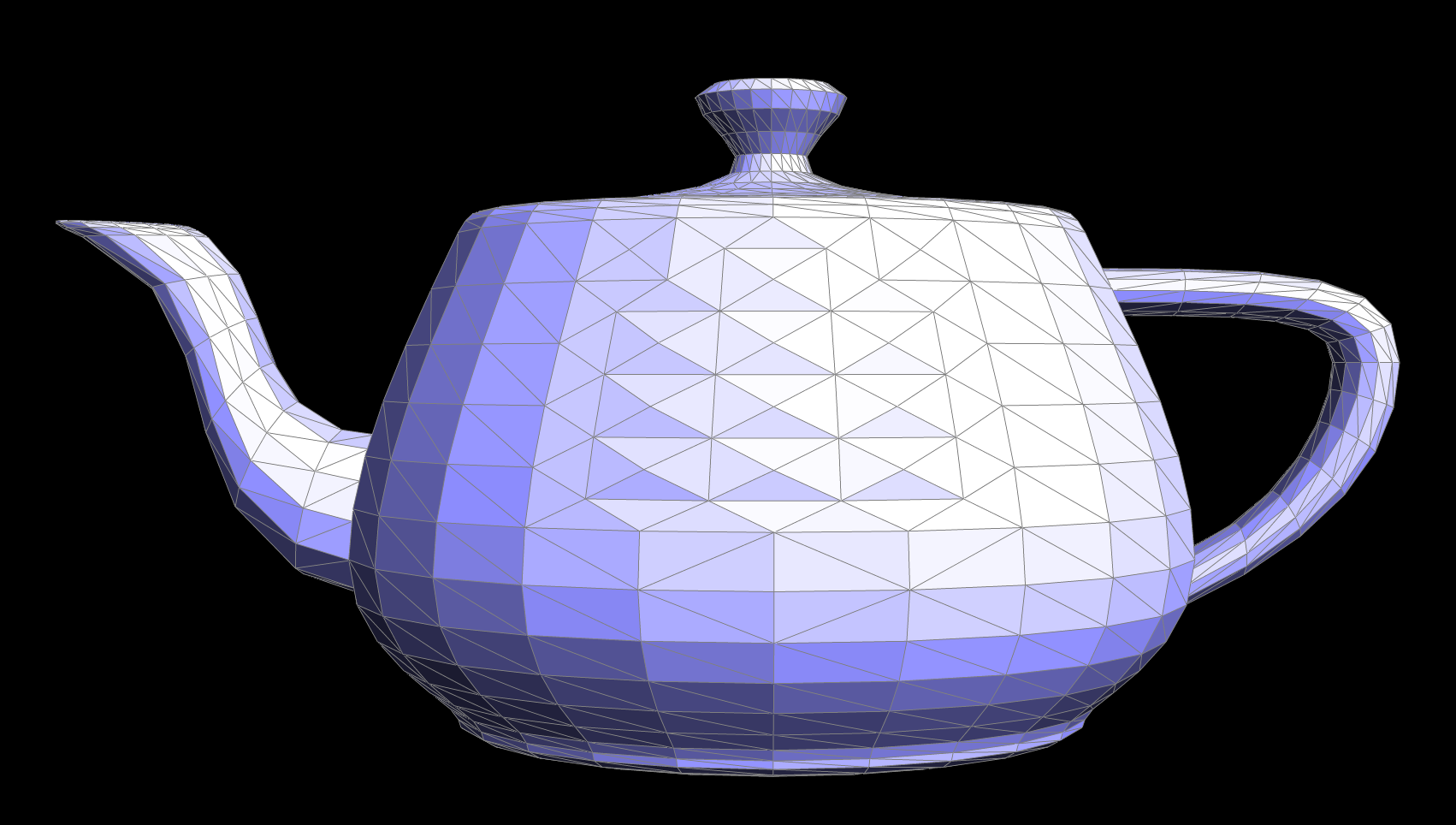
Phong Shading
Part 4: Edge Flip
1. Briefly explain how you implemented the edge flip operation and describe any interesting implementation / debugging tricks you have used.
In my implementation, I started by checking if the edge is a boundary edge. If it is, I returned the edge immediately without flipping. Otherwise, I retrieved the halfedges, vertices, and faces involved in the edge flip. Then, I swap the vertices connected by the edge and update the halfedges and their next pointers to maintain the cyclic structure of the faces. I also update the face pointers for each halfedge to ensure the correct faces are assigned after the flip. I also carefully managed the relationships between halfedges, vertices, and faces, ensuring that no references are lost. For debugging, I found it helpful to check the integrity of the mesh after each operation.
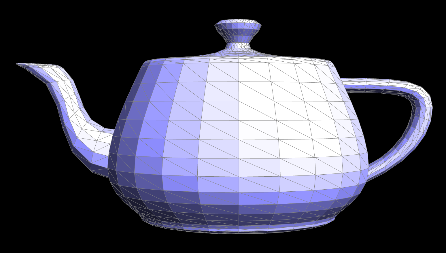
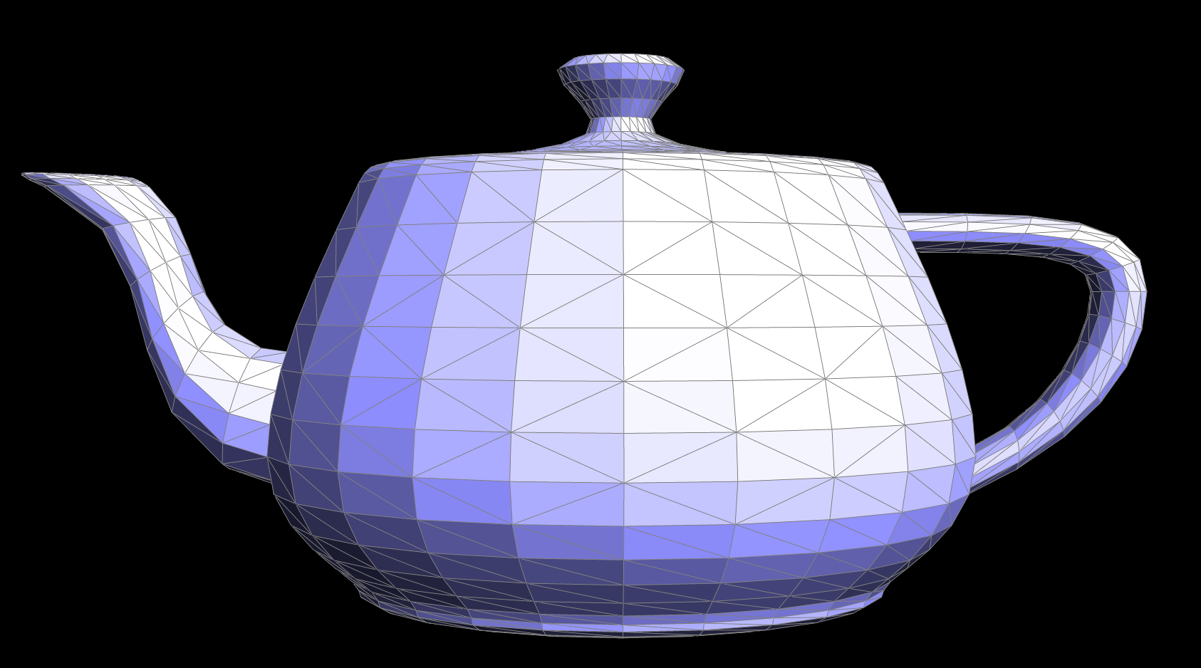
2. Show screenshots of the teapot before and after some edge flips.
Original teapot before edge flips
Teapot after some edge flips
Part 5: Edge Split
1. Briefly explain how you implemented the edge split operation and describe any interesting implementation / debugging tricks you have used.
I first handled the special case where the edge is on the boundary, returning early if necessary. Then, I identified and stored all relevant halfedges, vertices, edges, and faces associated with the edge being split. I created a new vertex at the midpoint of the edge and introduced four new edges and corresponding halfedges to properly integrate the new vertex into the mesh. I carefully reassigned halfedge twins, vertex references, and face assignments to ensure a consistent and valid halfedge data structure.
A key debugging trick I used was to visualize the halfedge connectivity step by step. I printed out halfedge and vertex assignments to track their relationships, ensuring that each new element was correctly linked. Testing with both simple and complex meshes helped catch issues like incorrect twin assignments or improper face updates.
2. Show screenshots of a mesh before and after some edge splits.
Original teapot before edge splits
Teapot after some edge splits
3. Show screenshots of a mesh before and after a combination of both edge splits and edge flips.
Original teapot before edge splits/flips
Teapot after some edge splits/flips
Part 6: Loop Subdivision for Mesh Upsampling
1. Briefly explain how you implemented the loop subdivision and describe any interesting implementation / debugging tricks you have used.
I first checked if the edge was on the boundary and returned early if necessary. I then identified and stored all relevant halfedges, vertices, edges, and faces associated with the edge being split. Instead of computing the midpoint manually, I used the newPosition already precomputed in the upsampling process and marked the new vertex accordingly.
Next, I created four new edges and corresponding halfedges, properly linking them to maintain a valid halfedge data structure. I also set flags to distinguish between new and existing edges, which was useful for subsequent operations like edge flipping. Ensuring correct face and halfedge assignments was crucial to maintaining mesh consistency.
An interesting debugging trick I used was to verify that every new vertex and edge was properly connected by iterating over the mesh and checking halfedge cycles. I also leveraged visualization tools to render the mesh after each split to confirm that the topology was correctly updated. Additionally, I tracked the isNew flags to ensure new edges were only flipped when necessary, preventing unintended mesh distortions.
2. Take some notes, as well as some screenshots, of your observations on how meshes behave after loop subdivision. What happens to sharp corners and edges? Can you reduce this effect by pre-splitting some edges?
After applying Loop subdivision, sharp edges and corners become increasingly rounded, and the overall shape appears smoother. By introducing additional edge loops (i.e., pre-splitting edges) around sharp features, we can preserve more of the original form by concentrating additional vertices and maintaining rigidity locally. This approach mitigates the otherwise pronounced smoothing effect, allowing us to retain crisp edges where desired.
Original Cube
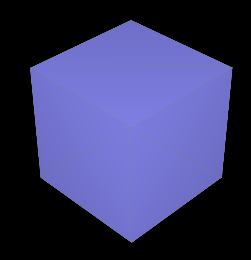
The original cube.
Upsampled twice
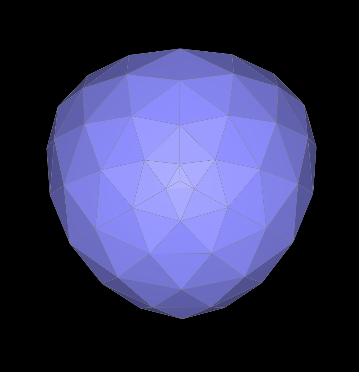
The cube after two upsampling.
Upsampled three times
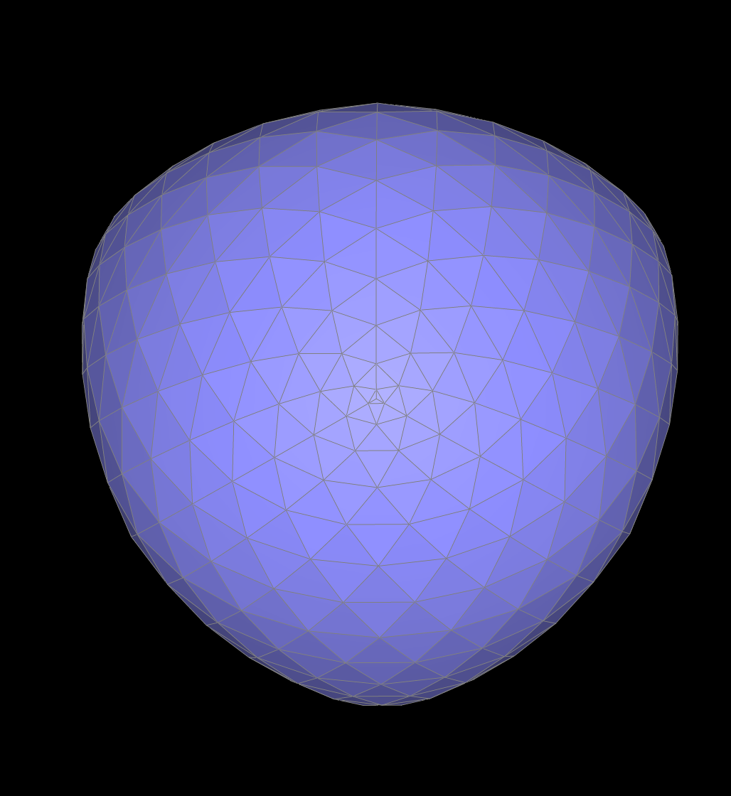
The cube after three upsampling.
3. Load dae/cube.dae. Perform several iterations of loop subdivision on the cube. Notice that the cube becomes slightly asymmetric after repeated subdivisions. Can you pre-process the cube with edge flips and splits so that the cube subdivides symmetrically? Document these effects and explain why they occur. Also explain how your pre-processing helps alleviate the effects.
The cube becomes slightly asymmetric after repeated Loop subdivision due to inconsistent initial triangulation, which causes uneven vertex placement. This happens because loop subdivision operates on triangles, and if the diagonals within the cube’s quad faces are not consistently aligned, different areas subdivide differently. To ensure symmetry, I pre-processed the cube by consistently flipping diagonal edges across all faces, ensuring a uniform triangulation pattern. Additionally, I strategically splitted the edges by adding supportive edge loops to help guide vertex placement evenly.
Original Cube
The original cube.
Upsampled once after pre-processing
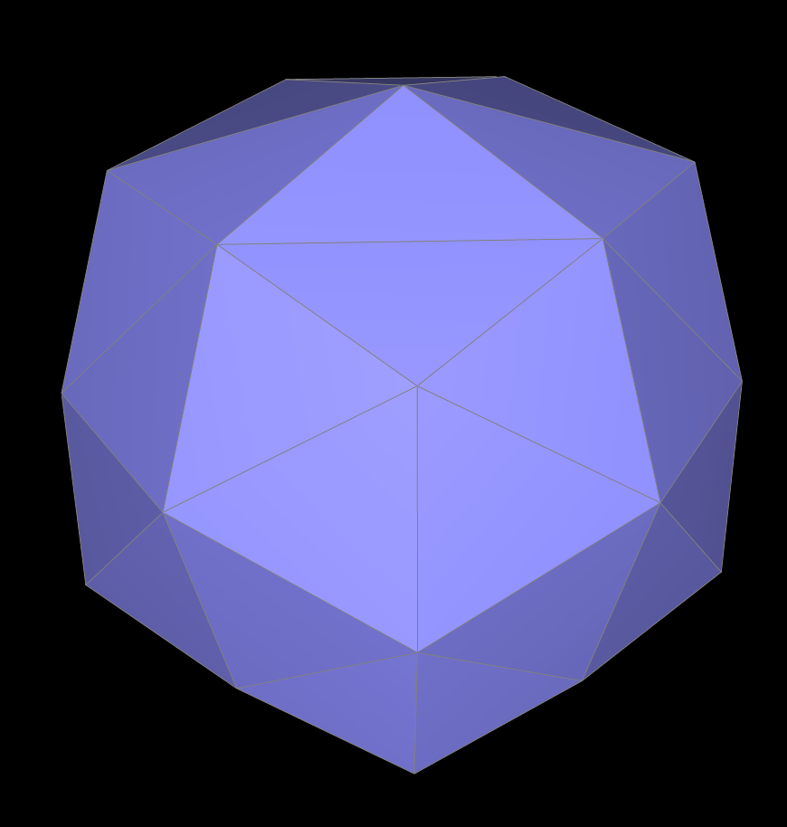
The cube after one upsampling.
Upsampled twice after pre-processing
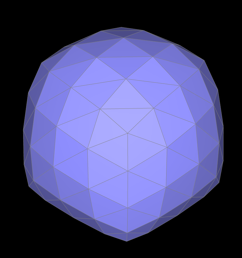
The cube after two upsampling.